Discrete High Side Mosfet Driver Circuit

Pdf Design Of High Side Mosfet Driver Using Discrete Components For 24v Operation

Driving High Side Mosfet Using Bootstrap Circuitry Part 17 17

Discrete And Integrated Amplifiers Amplifier Integrated Amplifier Electronics Circuit

Isolated Gate Drivers What Why And How Analog Devices

High Side Discrete Mosfet Driver All About Circuits

Discrete Implementation Of High Speed High Low Side Mosfet Driver Electrical Engineering Stack Exchange

Contrary to low side the high side configuration of mosfet requires some external circuitry to turn it on.
Discrete high side mosfet driver circuit.

Edn Mosfet Pair Makes Simple Spdt Switch
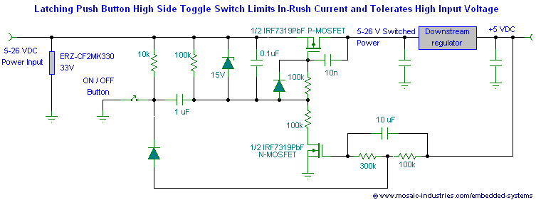
Push Button On Off Soft Latch Circuits Battery Powered Touch Toggle On Off Switch Momentary Button Mosfet Power Switch For Microcontrollers
How To Drive A Mosfet With An Optocoupler Electrical Engineering Stack Exchange

Discrete Class Ab Transistor Audio Power Amplifier Circuit Diagram This Is A Class Ab Transistor P Circuit Diagram Power Amplifiers Electronic Circuit Projects
Source : pinterest.com
